Validation / 1 of 10
Axial bar in tension
A straight bar pulled along its axis is the simplest problem in solid mechanics, so it is the first thing a solver has to get right. The answer involves only the load, the length, the cross-section and Young's modulus. If a solver gets this one wrong, the fault is in its bookkeeping (units, material, supports or how the load reaches the nodes), not in the finite element approximation.
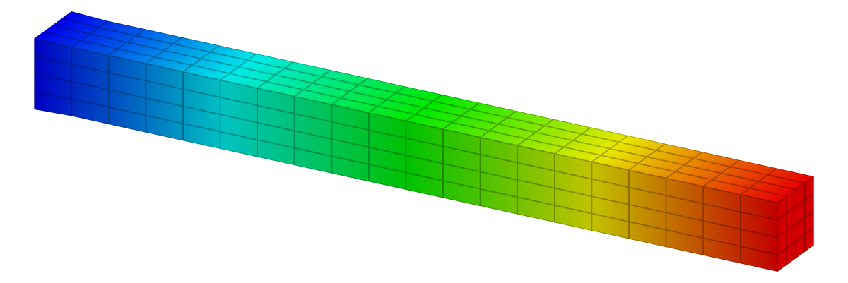
| Reference | KoFEM | Difference |
|---|---|---|
| 0.47619 mm | 0.47358 mm | −0.55 % within ±2 % |
The problem
| 1000 mm | |
| 100 × 100 mm | |
| 210 GPa | |
| 0.3 | |
| 1 MN |
| Supports | x = 0 face fixed (Ux, Uy, Uz). |
|---|---|
| Load | P in +x as a force on the x = L face. |
| Measured | Mean x-displacement of the x = L face. |
Analytical solution
Cut the bar at a section . Equilibrium of the part to the right of the cut needs an internal axial force , the same at every section, because nothing loads the bar between its ends. Assume that this force is carried by a normal stress that is uniform over the cross-section :
Hooke's law relates the stress to the axial strain, and the strain is the rate of change of the axial displacement :
With the clamp, , the displacement grows linearly along the bar,
and the loaded end moves by
With the inputs above, , the stress is and .
Two simplifications hide in this one-dimensional model. The stress is uniform over every section, and the lateral (Poisson) contraction is free everywhere. A 3-D solid meets neither exactly near its ends: the clamp prevents the contraction at , and at the loaded face the stress follows however the load is applied. By Saint-Venant's principle these disturbances die out within about one section width, so in a bar ten times longer than it is wide they change only slightly.
Finite element model
| Mesh | 20 × 4 × 4 grid: 320 linear 8-node hexahedra (P1) |
|---|---|
| Unknowns | 525 nodes, 1,575 degrees of freedom |
| Material | Linear elastic, isotropic |
| Solver | KoFEM engine (MFEM), the WebAssembly build the app runs: engine-5ceb743373dd |
The force is applied the way the app applies a force to a face: as a uniform traction , integrated over the 16 element faces of the end face. In the finite element method a traction enters through the work it does, so the force on node is
where is the shape function of that node. On linear quadrilateral faces of size , a node collects from each face it touches: an interior node of the end face gets , an edge node and a corner node . The forces add up to . Splitting equally over the nodes instead would get the total right but overload the edges and corners.
Results
| Quantity | tip extension δ |
|---|---|
| Reference | δ = P·L / (E·A) = 0.47619 mm |
| KoFEM | 0.47358 mm |
| Difference | −0.55 % within ±2 % |
Discussion
KoFEM's extension differs from by −0.55 %. Linear elements represent a linearly varying displacement exactly, so the uniform state inside the bar carries no discretisation error. What remains is the clamp. The x = 0 face is fully fixed, so near it the bar cannot contract sideways. That material is in a multiaxial state and stiffer than the 1-D model assumes, so the end moves slightly less. It is a difference between the 3-D body and the 1-D theory, so a finer mesh does not remove it.
The same bar under an end pressure comes out −0.55 %: the pressure path builds the same load vector.
Reproduce
In the app: open the model, then Studies → Static 1 → Run static solve, select the result plot and set Field to Ux. The Result summary shows Max Ux 4.736e-1 mm.
From a clone (Node.js 20+, bash, curl), this solves the model with the same engine and prints its line:
git clone https://github.com/mkofler96/KoFEM.git && cd KoFEM
bash scripts/fetch-wasm-engine.sh
node examples/validation/run.mjs --case axial-bar
Case Quantity FE Reference Err% Tol% Status
Axial bar in tension tip extension δ 0.47358 0.47619 -0.55 2 PASSReferences
- J. M. Gere and B. J. Goodno, Mechanics of Materials, Cengage Learning: axially loaded members, torsion, deflections of beams.
- S. P. Timoshenko and J. N. Goodier, Theory of Elasticity, 3rd ed., McGraw-Hill, 1970.
- T. J. R. Hughes, The Finite Element Method: Linear Static and Dynamic Finite Element Analysis, Dover, 2000.
KoFEM is research software and is not certified for safety-critical design. It solves linear-static, linear-elastic problems. Check results that matter against your own references.