Validation / 3 of 10
Cantilever beam, linear hexahedra
A beam clamped at one end and loaded at the other is the standard bending benchmark. Bending is where simple solid elements struggle, so this case tests the element as much as the solver.
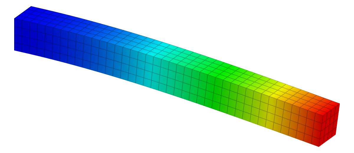
| Reference | KoFEM | Difference |
|---|---|---|
| −1.9048 mm | −1.8378 mm | −3.51 % within ±6 % |
The problem
| 1000 mm | |
| 100 × 100 mm | |
| 210 GPa | |
| 0.3 | |
| 10 kN |
| Supports | x = 0 face fixed (Ux, Uy, Uz). |
|---|---|
| Load | P in −y as a force on the x = L face. |
| Measured | Mean y-displacement of the x = L face. |
Analytical solution
Euler–Bernoulli beam theory assumes that cross-sections stay plane and perpendicular to the deformed axis, which neglects shear deformation. Take as the deflection, positive upwards, with the load acting downwards at the tip. Equilibrium of the part beyond a section gives the bending moment
and the curvature is proportional to it:
Integrating twice with the clamp conditions and gives the deflection curve
and at the tip
For this beam and .
Timoshenko beam theory adds the shear deformation that Euler–Bernoulli leaves out. For a cantilever with a tip load it adds a second term,
which is 0.78 % of the bending term for this beam (span ten times the depth). A converged 3-D solid model should therefore deflect slightly more than .
Finite element model
| Mesh | 40 × 4 × 4 grid: 640 linear 8-node hexahedra (P1) |
|---|---|
| Unknowns | 1,025 nodes, 3,075 degrees of freedom |
| Material | Linear elastic, isotropic |
| Solver | KoFEM engine (MFEM), the WebAssembly build the app runs: engine-5ceb743373dd |
The beam is meshed with linear 8-node hexahedra. Each element is a cube with sides one quarter of the beam depth. The tip load is a force on the end face, which the app integrates as a uniform traction.
Results
| Quantity | tip deflection δ |
|---|---|
| Reference | δ = P·L³ / (3·E·I) = −1.9048 mm |
| KoFEM | −1.8378 mm |
| Difference | −3.51 % within ±6 % |
Mesh convergence: Cantilever beam, P1 vs. P2
Linear elements lock in bending and approach from far below; quadratic ones are within a few percent on every mesh and level off slightly above the reference, since Euler–Bernoulli theory neglects shear deformation.
Data
| Order | Mesh | DOFs | KoFEM | Difference |
|---|---|---|---|---|
| P1 (linear) | 10 × 1 × 1 | 132 | −1.2339 mm | −35.22 % |
| P1 (linear) | 20 × 2 × 2 | 567 | −1.6682 mm | −12.42 % |
| P1 (linear) | 40 × 4 × 4 (this example) | 3,075 | −1.8378 mm | −3.51 % |
| P1 (linear) | 80 × 8 × 8 | 19,683 | −1.8879 mm | −0.88 % |
| P2 (quadratic) | 5 × 1 × 1 | 297 | −1.8847 mm | −1.05 % |
| P2 (quadratic) | 10 × 2 × 2 (this example) | 1,575 | −1.9398 mm | +1.84 % |
| P2 (quadratic) | 20 × 4 × 4 | 9,963 | −1.9330 mm | +1.48 % |
Discussion
KoFEM's deflection differs from the reference by −3.51 %: the linear elements are too stiff. The reason is shear locking. The edges of a linear hexahedron stay straight, so it cannot take the curved shape of a bent piece of beam; to bend at all, it has to shear. In a beam under pure bending the true shear strain is zero, so this spurious, parasitic shear stores strain energy that the real beam does not have, and the element is too stiff. The longer the element compared with the depth it spans, the worse it gets.
Refining the mesh cures it slowly. In the convergence study above the linear-element error goes −35.22 % → −12.42 % → −3.51 % → −0.88 % as the element size halves, approaching a factor of four per step: the second-order convergence of displacements with linear elements, once locking is under control.
Quadratic elements can bend, so they do not lock; see the quadratic hexahedra and the beam meshed from a STEP file. Their series settles near +1.48 %, above the reference. About +0.78 % of that is the shear deformation that Euler–Bernoulli theory leaves out. The rest comes from the 3-D stress state at the clamped root and the loaded end.
Reproduce
In the app: open the model, then Studies → Static 1 → Run static solve, select the result plot and set Field to Uy. The Result summary shows Min Uy -1.838e+0 mm.
From a clone (Node.js 20+, bash, curl), this solves the model with the same engine and prints its line:
git clone https://github.com/mkofler96/KoFEM.git && cd KoFEM
bash scripts/fetch-wasm-engine.sh
node examples/validation/run.mjs --case cantilever
Case Quantity FE Reference Err% Tol% Status
Cantilever beam, linear hexahedra tip deflection δ -1.8378 -1.9048 -3.51 6 PASSReferences
- J. M. Gere and B. J. Goodno, Mechanics of Materials, Cengage Learning: axially loaded members, torsion, deflections of beams.
- S. P. Timoshenko, “On the correction for shear of the differential equation for transverse vibrations of prismatic bars”, Philosophical Magazine 41 (1921) 744–746.
- R. D. Cook, D. S. Malkus, M. E. Plesha and R. J. Witt, Concepts and Applications of Finite Element Analysis, 4th ed., Wiley, 2002.
- T. J. R. Hughes, The Finite Element Method: Linear Static and Dynamic Finite Element Analysis, Dover, 2000.
KoFEM is research software and is not certified for safety-critical design. It solves linear-static, linear-elastic problems. Check results that matter against your own references.