Validation / 9 of 10
Plate with a hole, shell elements
The plate with a hole, modelled as a thin-walled part usually is: one layer of shell elements on the mid-surface, with the thickness as a property, instead of solid elements through the thickness. Loaded in its own plane, the shell carries the load as membrane stress, so Kirsch's is the reference here too.
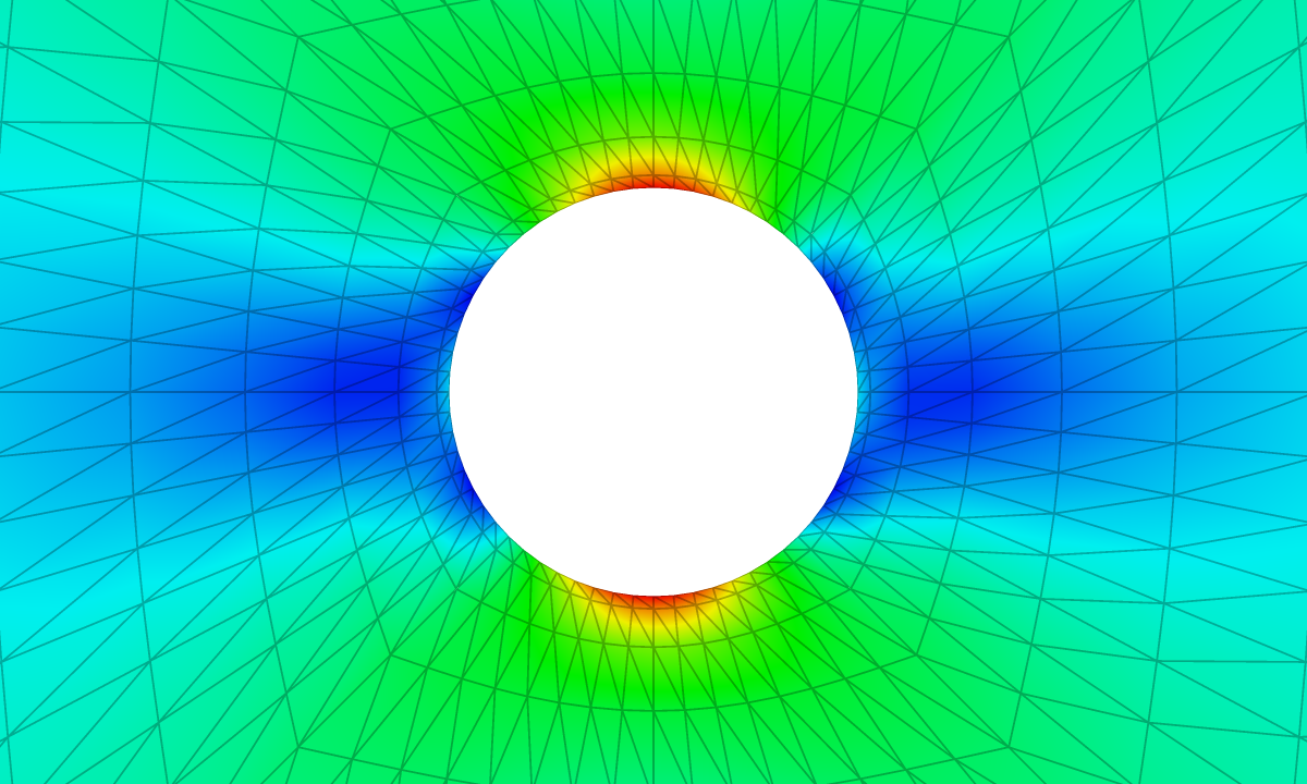
| Reference | KoFEM | Difference |
|---|---|---|
| 3.0000 | 2.9387 | −2.04 % |
The problem
| 1000 mm | |
| 10000 mm | |
| 500 mm | |
| 210 GPa | |
| 0.3 | |
| 100 MPa |
| Supports | x = −b edge fixed (all six DOFs). |
|---|---|
| Load | σ·2b·t in +x as a force on the x = +b edge. |
| Measured | Peak facet von Mises stress around the hole, divided by σ. |
Analytical solution
The derivation is on the solid plate's page. On the edge of the hole the hoop stress is , largest at , so . The solution is a plane-stress solution, which is exactly the state of a flat shell loaded in its plane.
Finite element model
| Mesh | O-grid, 12 rings × 64 around the hole, two triangles per quad: 1,536 3-node Kirchhoff shell triangles (DKT bending, CST membrane) |
|---|---|
| Unknowns | 832 nodes, 4,992 degrees of freedom |
| Material | Linear elastic, isotropic |
| Solver | KoFEM engine (MFEM), the WebAssembly build the app runs: engine-5ceb743373dd |
Each triangle combines a CST membrane, which carries in-plane loads with constant strain, and a DKT plate-bending element. In this load case only the membrane part works. The mesh is the solid plate's O-grid (12 rings × 64 around the hole) with every quad split into two triangles, so the hole edge is a polygon of 64 sides. Shell nodes carry six degrees of freedom, three translations and three rotations. The load is a force on the right edge, which the app spreads as a uniform line load .
Results
| Quantity | stress-concentration factor Kt |
|---|---|
| Reference | Kt = 3 (infinite plate) |
| KoFEM | 2.9387 |
| Difference | −2.04 % |
Discussion
KoFEM's differs from 3 by −2.04 %; the solid model of the same plate comes out −7.50 %. Both measure an element value, so both sit a little away from the edge, where the stress has started to fall. A CST triangle has one stress, at its centroid, and the first ring of triangles is split from thin quads, so half of its centroids sit a third of the way across the ring, closer to the edge than the centres of the solid hexahedra. That is one reason the shell gets nearer to 3 on the same grid.
The two models have 4,992 and 4,992 unknowns: the shell's 832 nodes carry six degrees of freedom each, the solid's 1,664 nodes three. Shells pay off when a thin wall bends: one layer of shell elements bends by construction, while solid elements need several layers through the thickness, or quadratic elements, to do the same (see the cantilever).
Reproduce
In the app: open the model, then Studies → Static 1 → Run static solve, select the result plot and set Field to Ux. The Result summary shows Max Ux 9.707e+0 mm.
From a clone (Node.js 20+, bash, curl), this rebuilds the model and its figure:
git clone https://github.com/mkofler96/KoFEM.git && cd KoFEM
bash scripts/fetch-wasm-engine.sh
cd web && bun install && bun run examples:generate-plate-hole-shell
References
- G. Kirsch, “Die Theorie der Elastizität und die Bedürfnisse der Festigkeitslehre”, Zeitschrift des Vereines deutscher Ingenieure 42 (1898) 797–807.
- S. P. Timoshenko and J. N. Goodier, Theory of Elasticity, 3rd ed., McGraw-Hill, 1970.
- J.-L. Batoz, K.-J. Bathe and L.-W. Ho, “A study of three-node triangular plate bending elements”, International Journal for Numerical Methods in Engineering 15 (1980) 1771–1812.
- R. D. Cook, D. S. Malkus, M. E. Plesha and R. J. Witt, Concepts and Applications of Finite Element Analysis, 4th ed., Wiley, 2002.
KoFEM is research software and is not certified for safety-critical design. It solves linear-static, linear-elastic problems. Check results that matter against your own references.