Validation / 7 of 10
Hollow shaft under torsion
Torsion of a circular tube is the shaft problem from every mechanics-of-materials course. Unlike the square bar, a circular section does not warp, so the 1-D theory is exact for the 3-D body away from the loaded end. That makes the case a clean test of how well a mesh represents a curved boundary.
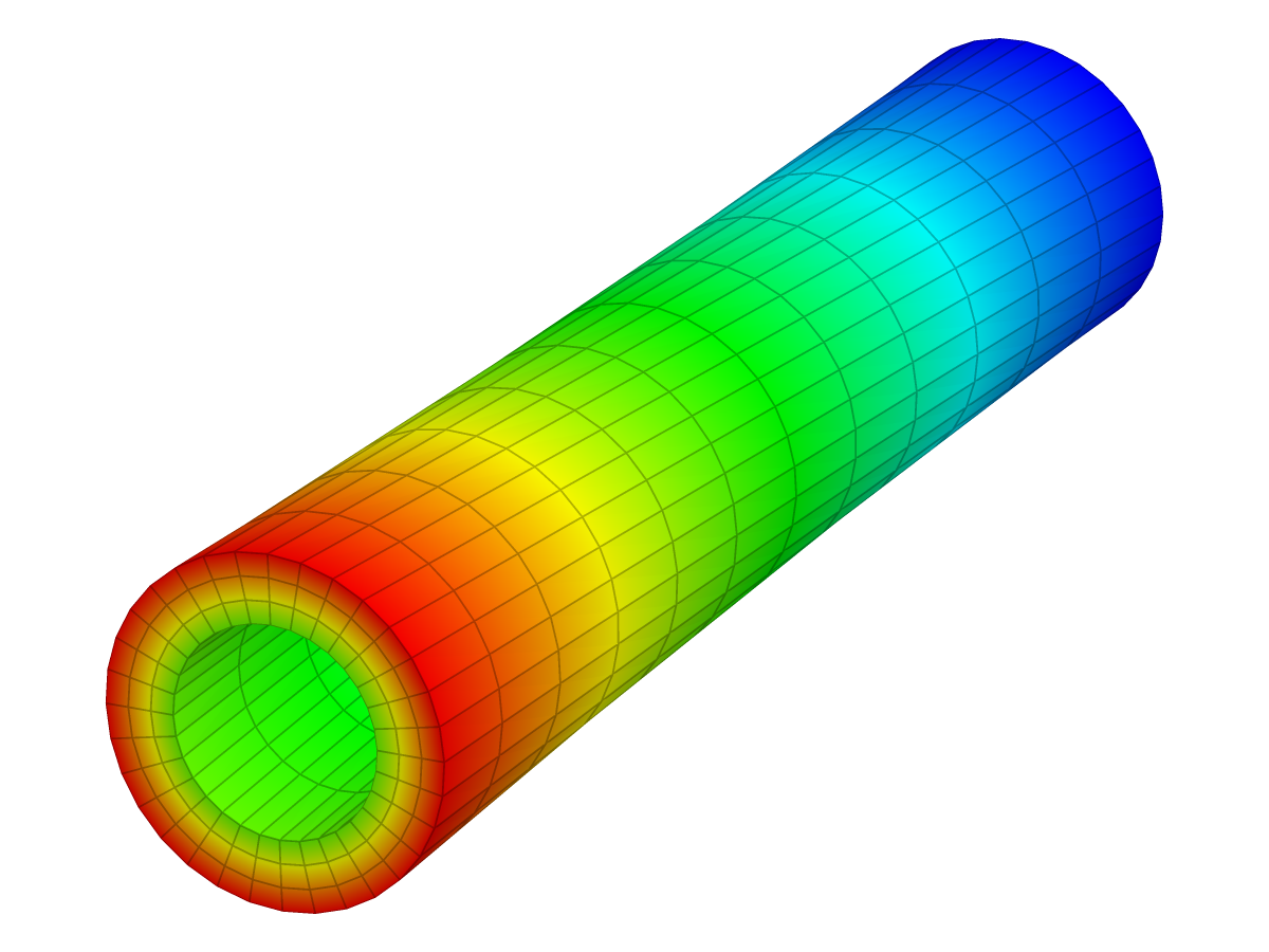
| Reference | KoFEM | Difference |
|---|---|---|
| 1.4489 × 10⁻³ rad | 1.4683 × 10⁻³ rad | +1.34 % within ±5 % |
The problem
| 500 mm | |
| 30 mm | |
| 50 mm | |
| 210 GPa | |
| 0.3 | |
| 2 kN·m |
| Supports | z = 0 end fixed (Ux, Uy, Uz). |
|---|---|
| Load | Torque T about z as a moment on the z = L end. |
| Measured | Mean rotation of the z = L end about the axis. |
Analytical solution
By symmetry, each section of a circular shaft stays plane and turns as a rigid disc. If the angle of twist grows at the rate along the axis, the material at radius is sheared by
The shear stress grows linearly from the inner to the outer surface. Its moment about the axis balances the applied torque,
with the polar moment of the annulus
Over the length the free end turns by
Here , and . The largest shear stress, at the outer surface, is .
Finite element model
| Mesh | 3 × 32 × 12 grid (radial × around × axial): 1,152 linear 8-node hexahedra (P1) |
|---|---|
| Unknowns | 1,664 nodes, 4,992 degrees of freedom |
| Material | Linear elastic, isotropic |
| Solver | KoFEM engine (MFEM), the WebAssembly build the app runs: engine-5ceb743373dd |
The tube is meshed with 3 elements through the wall, 32 around and 12 along the axis. The nodes lie on the true circles, but the element edges between them are straight. The torque is applied as tangential nodal forces on the end ring, proportional to the radius (the distribution of the exact solution) and scaled so the moment is , which is how the app applies a moment to a face. The twist is the mean rotation of the end-ring nodes.
Results
| Quantity | angle of twist θ |
|---|---|
| Reference | θ = T·L / (G·J) = 1.4489 × 10⁻³ rad |
| KoFEM | 1.4683 × 10⁻³ rad |
| Difference | +1.34 % within ±5 % |
Mesh convergence: Hollow shaft
The error falls steadily as the straight-sided elements approach the circle.
Data
| Order | Mesh | DOFs | KoFEM | Difference |
|---|---|---|---|---|
| P1 (linear) | 1 × 8 × 3 | 192 | 1.7832 × 10⁻³ rad | +23.08 % |
| P1 (linear) | 2 × 16 × 6 | 1,008 | 1.5259 × 10⁻³ rad | +5.31 % |
| P1 (linear) | 3 × 32 × 12 (this example) | 4,992 | 1.4683 × 10⁻³ rad | +1.34 % |
| P1 (linear) | 4 × 64 × 24 | 24,000 | 1.4546 × 10⁻³ rad | +0.39 % |
Discussion
KoFEM's twist differs from the reference by +1.34 %, and almost all of it is geometry. With straight element edges, the section of the mesh is the ring between two regular polygons inscribed in the true circles. Its polar moment is smaller than , so it twists more. The polar moment of a regular -gon inscribed in a circle of radius is
which tends to as grows. The twist the polygon alone predicts, , matches KoFEM's error on every mesh of the convergence study:
| Segments | Polygon alone | KoFEM |
|---|---|---|
| 8 | +23.09 % | +23.08 % |
| 16 | +5.29 % | +5.31 % |
| 32 | +1.29 % | +1.34 % |
| 64 | +0.32 % | +0.39 % |
What the elements add on top is under a tenth of a percent. The geometric error falls with the square of the segment angle, which is the factor of four per refinement in the convergence plot. More segments, or curved higher-order elements, remove it. The same holds for any curved surface in a model: the mesh replaces it with facets, and stiffness follows the facets.
Reproduce
In the app: open the model, then Studies → Static 1 → Run static solve, select the result plot and set Field to Displacement (magnitude). The Result summary shows Max |U| 7.343e-2 mm.
From a clone (Node.js 20+, bash, curl), this solves the model with the same engine and prints its line:
git clone https://github.com/mkofler96/KoFEM.git && cd KoFEM
bash scripts/fetch-wasm-engine.sh
node examples/validation/run.mjs --case shaft-torsion
Case Quantity FE Reference Err% Tol% Status
Hollow shaft under torsion angle of twist θ 1.4683e-3 1.4489e-3 +1.34 5 PASSReferences
- J. M. Gere and B. J. Goodno, Mechanics of Materials, Cengage Learning: axially loaded members, torsion, deflections of beams.
- S. P. Timoshenko and J. N. Goodier, Theory of Elasticity, 3rd ed., McGraw-Hill, 1970.
KoFEM is research software and is not certified for safety-critical design. It solves linear-static, linear-elastic problems. Check results that matter against your own references.