Validation / 5 of 10
Cantilever beam from a STEP file
The cantilever again, but built the way you build a model in the app: import a STEP block, mesh it, fix one end face and load the other. The mesh is an unstructured Netgen mesh of tetrahedra rather than a hand-made grid. The model opens ready to solve, and after the solve the Results panel compares the tip deflection with the hand formula.
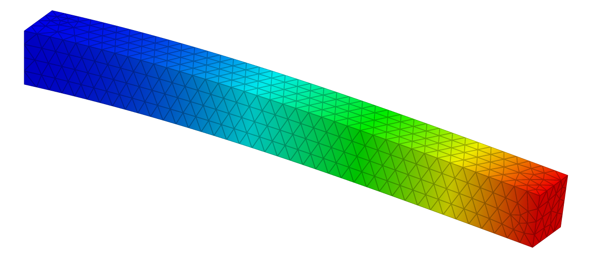
| Reference | KoFEM | Difference |
|---|---|---|
| −1.9048 mm | −1.9040 mm | −0.04 % |
The problem
| 1000 mm | |
| 100 × 100 mm | |
| 210 GPa | |
| 0.3 | |
| 10 kN |
| Supports | x = 0 face fixed (Ux, Uy, Uz), picked as one CAD face. |
|---|---|
| Load | P in −y as a force on the x = L face, picked as one CAD face. |
| Measured | Mean y-displacement of the x = L face. |
Analytical solution
Euler–Bernoulli beam theory assumes that cross-sections stay plane and perpendicular to the deformed axis, which neglects shear deformation. Take as the deflection, positive upwards, with the load acting downwards at the tip. Equilibrium of the part beyond a section gives the bending moment
and the curvature is proportional to it:
Integrating twice with the clamp conditions and gives the deflection curve
and at the tip
For this beam and .
Timoshenko beam theory adds the shear deformation that Euler–Bernoulli leaves out. For a cantilever with a tip load it adds a second term,
which is 0.78 % of the bending term for this beam (span ten times the depth). A converged 3-D solid model should therefore deflect slightly more than .
Finite element model
| Mesh | Netgen, 25 mm maximum element size: 2,991 quadratic 10-node tetrahedra (P2) |
|---|---|
| Unknowns | 5,532 nodes, 16,596 degrees of freedom |
| Material | Linear elastic, isotropic |
| Solver | KoFEM engine (MFEM), the WebAssembly build the app runs: engine-5ceb743373dd |
Netgen meshes the block with a 25 mm maximum element size, about 4 elements across the section. The elements are quadratic: linear tetrahedra lock in bending even more than the linear hexahedra do. The support and the load are each one CAD face, picked with one click, so they stay on the model when you change the element size and mesh it again. The deflection is the mean of the loaded face, which is what the app's hand check reads.
Results
| Quantity | tip deflection δ |
|---|---|
| Reference | δ = P·L³ / (3·E·I) = −1.9048 mm |
| KoFEM | −1.9040 mm |
| Difference | −0.04 % |
Discussion
KoFEM's tip deflection differs from by −0.04 %. The beam-theory value is not the whole story: the shear deformation it leaves out adds +0.78 %, so a converged solid model would deflect slightly more. Against the Timoshenko value the result differs by −0.81 %, which is what the mesh still leaves out at this element size.
The quadratic hexahedra on a coarse grid come out +1.84 %. Both show the same thing: in bending, second-order elements are accurate on meshes coarse enough to solve in a second.
Reproduce
In the app: open the model, then Studies → Static 1 → Run static solve, select the result plot and set Field to Uy. The Result summary shows Min Uy -1.904e+0 mm.
From a clone (Node.js 20+, bash, curl), this rebuilds the model and its figure:
git clone https://github.com/mkofler96/KoFEM.git && cd KoFEM
bash scripts/fetch-wasm-engine.sh
cd web && bun install && bun run examples:generate-cantilever
References
- J. M. Gere and B. J. Goodno, Mechanics of Materials, Cengage Learning: axially loaded members, torsion, deflections of beams.
- S. P. Timoshenko, “On the correction for shear of the differential equation for transverse vibrations of prismatic bars”, Philosophical Magazine 41 (1921) 744–746.
- J. Schöberl, “NETGEN: An advancing front 2D/3D-mesh generator based on abstract rules”, Computing and Visualization in Science 1 (1997) 41–52.
- R. D. Cook, D. S. Malkus, M. E. Plesha and R. J. Witt, Concepts and Applications of Finite Element Analysis, 4th ed., Wiley, 2002.
KoFEM is research software and is not certified for safety-critical design. It solves linear-static, linear-elastic problems. Check results that matter against your own references.